Wattstopper Power Pack Wiring Diagram
Wattstopper How To Wiring A Bz 150 Universal Voltage Power Pack Youtube
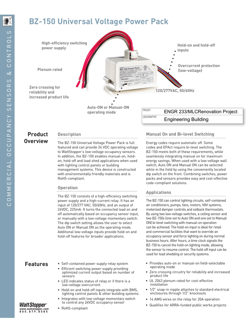
Bz 150 Universal Voltage Power Pack S Trol N

Wattstopper How To Wire A Dt 305 Dual Technology Ceiling Sensor Youtube

Sx 2201 Watt Stopper Bz 150 Wiring Diagram Get Free Image About Wiring Wiring Diagram

Fb 9427 Wattstopper How To Wiring A Bz150 Universal Voltage Power Pack Free Diagram

Diagram Battery Pack Diagram Full Version Hd Quality Pack Diagram Fusddit37648 Lineaceramicaparma It

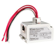
The power pack is attached to existing junction boxes or mounted into fixture wiring trays.
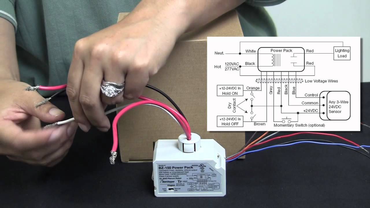
Wattstopper power pack wiring diagram. 12 18 awg cu only strip gage 1 2 12 7mm. The bz 150 supplies low voltage power to occupancy sensors and other control devices switching line voltage in response to signals from control devices. Low voltage wiring should use at least 22 gauge wire. Wattstopper wiring diagrams temperature control systems is a full line the mpp ceiling sensor power pack is the foundation for any low voltage lighting the bz power pack switches connected loads on and off in response to wattstopper low voltage occupancy sensors.
High voltage connections should use at least 14 gauge. Always check local building codes. High voltage connections should use at least 14 gauge. Wiring directions each wattstopper bz series power pack can supply power for 7 dt 305 sensors.
After initial wiring is complete check wiring diagram to verify power pack is wired correctly. 3 most applications require ul listed 18 22 awg 3 conductor class 2 cables for low voltage wiring. The power pack is attached to existing junction boxes or mounted into fixture wiring trays. 1 all wattstopper power packs should be installed in accordance with state.
2 power packs are designed to attach to existing or new electrical enclosures with 5 125 40mmj knockout check electrical codes in your area. Always check local building codes. Connect the low voltage. Local and national electrical codes and requirements.
Refer to the wiring diagram on the next page for the following procedures. The power pack is attached to existing junction boxes or mounted into fixture wiring trays. The power pack is attached to existing junction boxes or mounted into fixture wiring trays. When using more sensors than this multiple power packs are required.
Visit our website for faqs. 2 power packs are designed to attach to existing or new electrical enclosures with 5 125 40mmj knockout check electrical codes in your area. Red wire 24vdc from power pack to the 24v terminal on the sensor. Before installing the power pack.
After initial wiring is complete check wiring diagram to verify power pack is wired correctly. For the bz 50 low voltage wiring should use at least 22 gauge wire. Low voltage wiring should use at least 22 gauge wire high voltage connections should use at least 14 gauge. Description the bz 150 power packs is the foundation for any low voltage lighting control system.
Always check local building codes. High voltage connections should use at least 14 gauge.

Testing A Bz 50 Wattstopper Power Pack Bz50 Simple Check Out Test Lighting Controls Youtube

Wattstopper Elcu 200 Emergency Lighting Cnotrol Unit Power Pack White Toomanyamps

Ax 8163 Watt Stopper Wiring Diagrams Also Motion Sensor Light Wiring Diagram Wiring Diagram
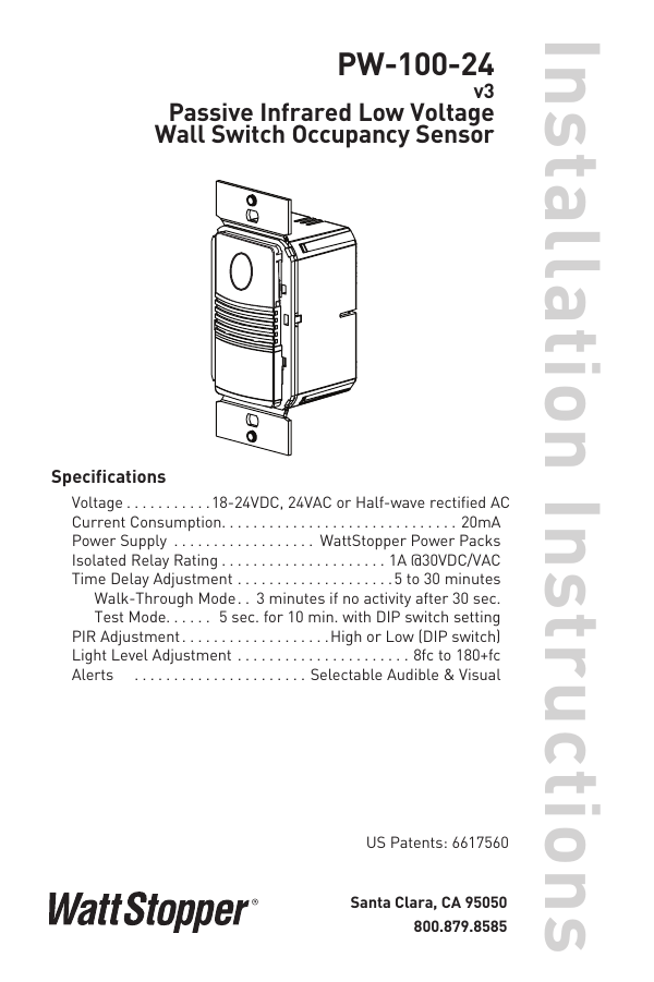
Diagram Watt Stopper Occupancy Sensor Wiring Diagram Full Version Hd Quality Wiring Diagram Fishbonediagramexample Popup Galerie Fr
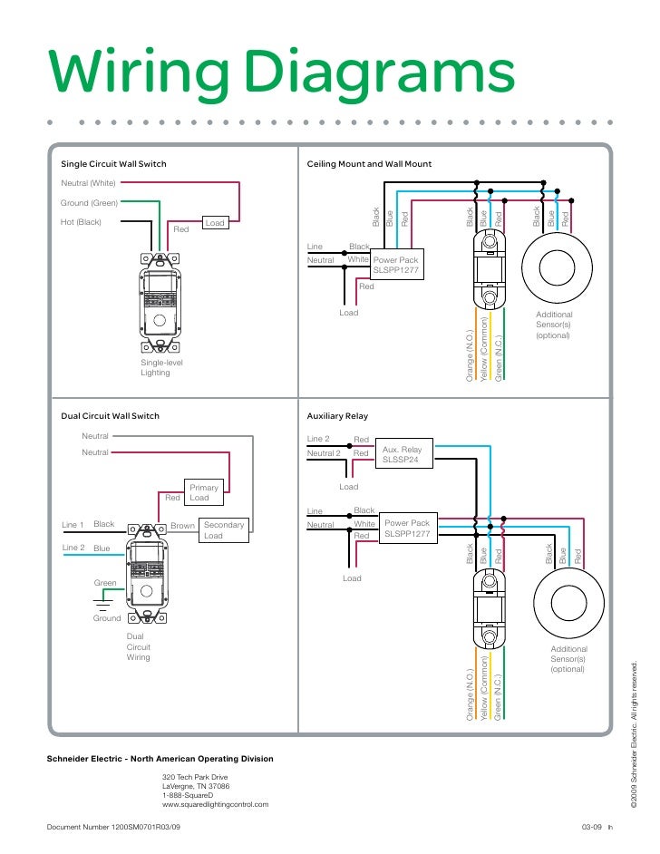
Diagram Wall Occupancy Sensor Wiring Diagram Picture Full Version Hd Quality Diagram Picture Mac5501gschematic3179 Concessionariabelogisenigallia It

Et 5812 Extech Wiring Diagrams Download Diagram

Installation Instructions Power Packs B120 B277 B347 Manualzz
Kele Com Watt Stopper Legrand Bz 150 Lighting Controls Occupancy Sensors Relay Power Packs

Wattstopper B277e P Power Pack Accessories Occupancy Sensors Lighting Controls Platt Electric Supply

St 0018 Watt Stopper Wiring Diagrams Also Motion Sensor Light Wiring Diagram Wiring Diagram

Diagram Alpine Power Pack Wiring Diagram Ktp 445u Full Version Hd Quality Ktp 445u Kitprogschematic8127 Beautywell It

Pin On Schema Cablage

Diagram Cooper Occupancy Sensor Switch Wiring Diagram Full Version Hd Quality Wiring Diagram Diagramsrus Artemismail Fr

