Vav Box Control Sequence

Typical Control Sequence For A Pressureindependent Vav Box With Download Scientific Diagram
Vav Box Control Ashrae 90 1 And You
Http Www Ashraeiowa Org Wp Content Uploads 2013 08 Advanced Vav Control Sequences 2013 11 12 Secured Pdf
5 6 Hvac Zone Level Systems
Improve Your Vav Control Strategy To Improve Your Bottom Line Fmlink
Nr 4 5 Hvac System Control Requirements
A dual duct box has inlets control dampers.
Vav box control sequence. Coordinate with electrical lighting design for dual use. Vav box control logic. Use zone occupancy sensors for unoccupied mode whenever possible. Provide the following for all air terminal unit boxes.
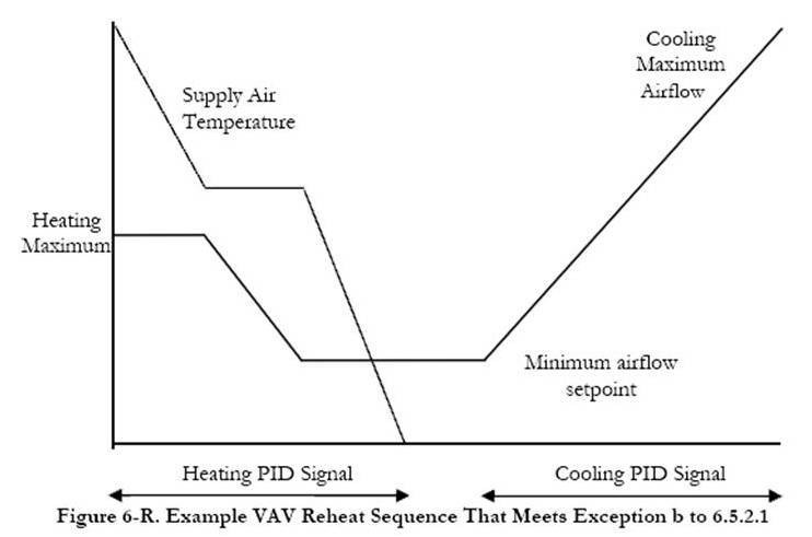
Johnson controls ddc for bacnet or n2 etc. Typical sequence of operation for a vav box non fan powered heating and cooling mode heating mode sequence of operation non fan powered on call for heat from the thermostat a signal is sent to the ddc controller. From the most basic to the most sophisticated sequence of operation the controls are designed by experts in vav single duct terminal operation. Vav boxes with reheat coils were traditionally controlled using the con trol logic shown in.
Patented flowstartm airflow sensor standard electric control box. The intent is for this sequence to be included in the contract drawings. It is a commercially manufactured box with a control damper inlet and outlet connections and options such as flow pickups return air plenum inlet heating coil and fan. Vav box control sequences ahu control sequences zone groups dp setpoint reset sat setpoint reset outdoor air control minimum outdoor air control demand controlled ventilation automatic fault detection and diagnostics alarms.
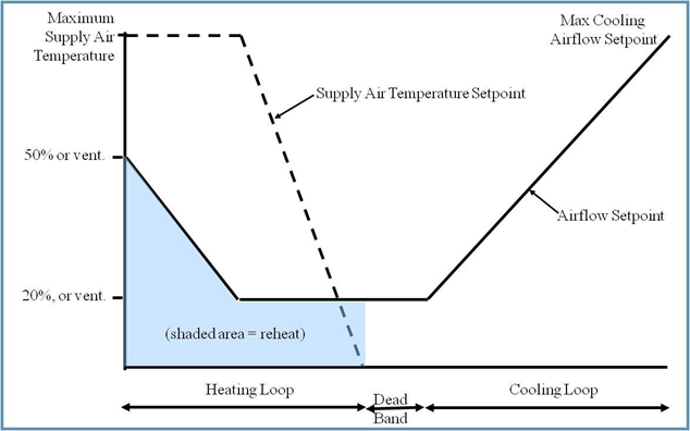
Vav terminal unit commonly called a vav box this mechanical equipment modulates airflow to the space with the johnson controls vav controller. Vav boxes with hot water reheat. So in the sequence of operation for a fan powered vav box and a non fan powered vav box would include closing the damper to allow minimal air from the air handler and at the same time energize the fan contactor so that the fan in the vav box comes on and pulls warmer air from the plenum. Conventional vav box logic.
Reference standard control diagrams ic 16.

Typical Uses Hvac Vav System
Nr 4 5 Hvac System Control Requirements
What S The Difference Between Vav Vs Vvt Hvac Systems Hvac Brain Northrich Parts

Flow Chart Of Proposed Control Algorithms With Variable Minimum Airflow Download Scientific Diagram
Https Www Downloads Siemens Com Download Center D Tec Controller Terminal Box Controller Vav Electronic Output Owner S Manual A6v10435984 Us En Pdf Mandator Ic Bt Segment Hq Fct Downloadasset Pos Download Id1 A6v10435984

Supply Air Temperature An Overview Sciencedirect Topics
Https Webselect Johnsoncontrols Com Helpfiles Webselect 20vav 20selection 20user 20manual Jci Pdf
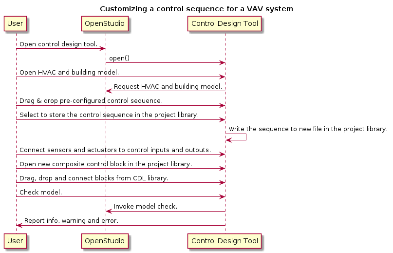
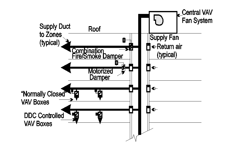
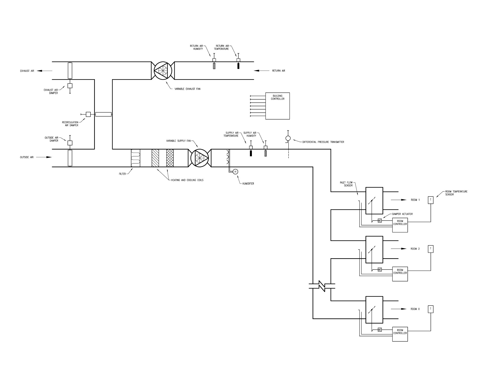
4 Use Cases Openbuildingcontrol
Https Www Amca Org Assets Resources Public Pdf Taylor 20vav 20design 20tips Pdf
Https Cgproducts Johnsoncontrols Com Met Pdf 12012070 Pdf X 93 X 93

11 Example Application Openbuildingcontrol

B Cusum Control Chart For The Data In A With K 0 5 And H 5 Download Scientific Diagram

How Vav Boxes Work Hvac Commercial Zoning Step By Step

